
An enquiry marked “three-phase” but missing voltage leaves a supplier unable to identify the required winding connection. Capacity matters, but the machine must supply the correct circuit. Clear electrical fields turn a broad product request into a selection task that an engineer can actually answer.
Choosing a 3 phase alternator starts by translating the equipment schedule into voltage, current, and load characteristics. A marine alternator adds vessel-specific drive interfaces and environmental exposure to the enquiry. Those operating details let the supplier relate the requested electrical component to its drive, loads, and installation environment.
Give Each Electrical Field a Clear Meaning
Line voltage is measured between two phase conductors; phase voltage refers to the voltage across an individual winding. In a balanced star connection, line voltage is the square root of three times phase voltage. In delta, each winding spans two lines. Connection and neutral requirements complete that voltage entry.
Equal phase loading is another specification issue. Single-phase services connected to a three-phase supply can leave one winding carrying more current than the others. The total load may appear acceptable while an individual phase approaches its limit. A marine alternator enquiry therefore benefits from a phase-by-phase load schedule, where lighting and auxiliaries are distributed unevenly.
Power factor states the ratio of active power in kW to apparent power in kVA. Lower power factor raises the current needed for the same active demand at a given voltage. A 3 phase alternator enquiry records the load’s power requirement and its operating power factor separately.
Total harmonic distortion, or THD, describes departure from a sinusoidal waveform. Voltage THD and current THD are different measurements: distorted load current can produce voltage distortion through the supply impedance. Voltage-quality limits therefore need an identified load condition. A waveform figure obtained under one condition cannot describe every connected equipment mix.
Let the Load Describe the Excitation Requirement
Resistive heaters mainly draw active power, whereas motors introduce lagging reactive demand and capacitors can create leading demand. These characteristics change the excitation needed to maintain voltage. Excessive leading loading can push operation outside the alternator’s capability. The combined load at each operating stage matters more than assigning one label to an entire installation.
Brushless construction and self-excitation describe different features. A brushless machine uses an exciter and rotating rectifiers to supply the rotor field without brushes. Self-excitation normally derives regulator power from the main output. For a 3 phase alternator, that distinction identifies the excitation architecture without confusing its mechanical arrangement with the source of regulator power.
An enquiry can specify independent excitation-control power through a permanent magnet generator, or PMG. That separation preserves regulator power when main-terminal voltage falls under demanding loads. Auxiliary-winding excitation is another available arrangement. The appropriate marine alternator configuration follows the starting sequence, reactive demand, and acceptable voltage disturbance; PMG alone does not specify the required performance.
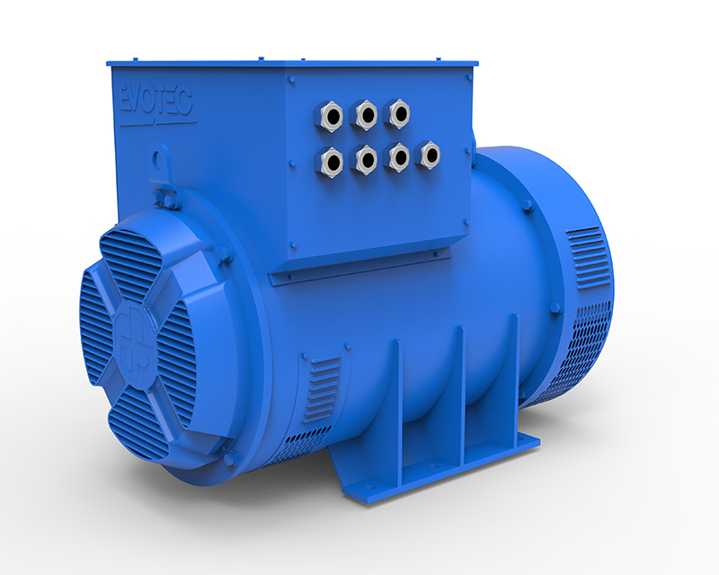
Starting dip and recovery enter the enquiry alongside load sequence and power factor; steady accuracy is a separate entry. For EvoTec Power‘s TCM368, the enquiry requests a choice among self-excitation, auxiliary winding, and PMG. TCM368 lists steady voltage regulation of ±0.5% and THD below 3%.
The two-thirds-pitch winding addresses waveform distortion. The regulator entry records stability adjustment, low-frequency compensation, interference filtering, and remote voltage trim from the associated ETC range. For parallel operation, an enquiry identifies ETC-2 or ETC-3 and the required paralleling and over-excitation functions. Naming the regulator with its excitation arrangement records the control configuration for the proposed installation.
Resolve the Drive Connection and Local Exposure
Installation conditions can exclude an electrically suitable machine before the load is ever connected. Housing dimensions, bearing arrangement, mounting geometry, and the drive coupling determine physical compatibility. SAE identification provides a standardized interface reference, but the particular housing and coupling sizes still need to match the prime mover’s assembly drawings.
EvoTec Power specifies SAE arrangements for TCM368, providing a practical interface reference. A marine alternator also needs room for its cooling openings and terminal access. The mounting and coupling details for a 3 phase alternator can then be reviewed together before an interface mismatch is discovered during assembly.
Humidity and dust require an exposure description that goes beyond a marine label. TCM368 has standard IP23 protection; this is not a dust-tight specification. Optional marine varnish addresses moisture, mould, and fog resistance. Surface treatment and enclosure protection serve different purposes, so anticipated contaminants and water exposure need separate entries in the enquiry.
Temperature limits and monitoring options add installation detail. TCM368 uses Class H insulation and lists winding and bearing temperature sensors as options. Ambient temperature, airflow, and the desired monitoring functions complete the environmental description. Protective accessories must be identified explicitly rather than inferred from the insulation class.
Send an Enquiry That Can Be Answered
A completed enquiry connects the load schedule with voltage, frequency, shaft speed, bearing arrangement, and installation drawings. It identifies the required marine alternator configuration and the voltage-quality conditions expected from the 3 phase alternator. EvoTec Power can then respond against defined electrical and mechanical inputs. The reply can identify an excitation arrangement and interface for the specified assembly.
